Transforming a Channel🔗
Most scalars that come from external inputs can be transformed into other values. This can be useful for:
-
Transforming MPVI interface A/D voltage into Equivalence Ratio, Air/Fuel Ratio, Temperature, Pressure, ...
-
Transforming a Serial input Equivalence Ratio into an Air/Fuel ratio
-
Transforming a raw external input value into a parameter value
Bringing up the Transform Menu🔗
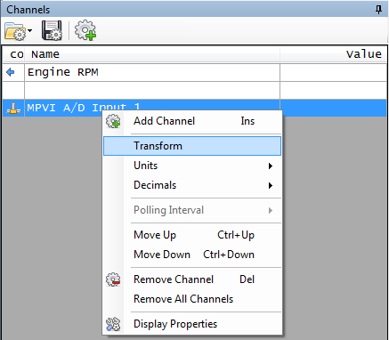
On the Channel display, you can right click a channel to bring up the menu. If the channel supports transformation, you will see an option called "Transform".
Selecting your Transform🔗
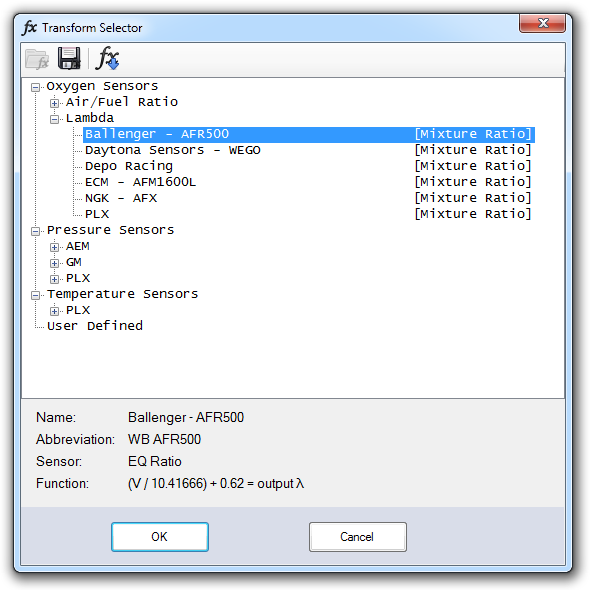
The Transform Selector form will show you any transforms that apply to the channel you have selected.
For example, if your base channel is a voltage input, the Transform Selector will show you transforms that take voltage as the input.
Defining your own Transform🔗
If your sensor is not defined in our list, or you must account for a signal/noise offset, you can define your own transform.
In this example, I first selected Ballenger - AFR500, then clicked the Fx to copy it down into the User Defined area. This gives me a starting point close to my input sensor. Then, you can add any offsets needed for your specific installation.
You must select a parameter and units. The transform will convert the input source into an output of type of the parameter you selected, with the associated units. When adding this transform into your layout displays, you simply add the Parameter you've transformed your input to.
The user transform values you input will be stored with the channel, and will be saved any time you save your channel config.
-
In the Transform Selector window, select a sensor that is similar to the sensor you wish to add.
-
Click the
 button to copy the selected sensor's parameters into the fields at the bottom of the window. (This should give you a starting point close to the sensor you want to add.)
 -
Click the Parameter link. The Parameter Selector window appears.
-
Double-click on the parameter that you wish map your sensor output to.
Note
- The transform will convert the input source into an output of the type of the parameter you selected. When adding channels that use this transform to your layout displays, you simply add the parameter you specified here.
-
In the dropdown to the right of the Parameter link, select the units for the output parameter.
-
Use the Function fields to specify how the range of values output by the connected sensor should be transformed into the range of values for the selected parameter.
-
Enter a Description for this transform.
-
Click Ok.
Note
- The user transform values you input will be stored with the channel, and will be saved any time you save your channel config.
- If your transform is not listed in our default list, we'd like to add it for you. Please contact our support team.
Defining The Function🔗
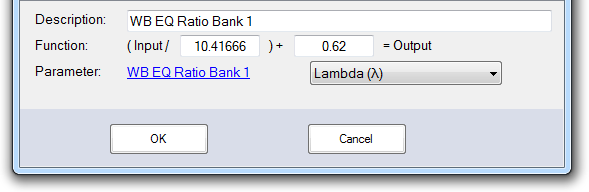
The Function fields define how the numerical values associated with the input are converted to their corresponding output values. In the sample screen above, the function is converting values in the range 0-5 (volts) to values in the range 0.62-1.10 (Lambda).
To define the function, you just need two known input values and their corresponding output values. Consult the documentation for the device whose output you are transforming.
Once you have these values, the number to put in the first box can be calculated with the following formula:
- (Input2 - Input1) / (Output2 - Output1)
If we used the max and min values from the example above, you would get:
- (5 - 0 volts) / (1.10 - 0.62 lambda) = 10.41666
To determine the value of the second box, you simply plug either of the two known input and output pairs into the resulting equation and solve for the missing value.
In our example, if you insert the 0 volt input and it corresponding output value, you get:
- 0/10.4166 + X = 0.62.
- So, X = 0.62.