Ignition & Injection Wiring🔗
The suggested ignition and injection wiring can be found in the below order. Users may configure the firing order in the “Cylinder Firing Order” table within VCM Live but the pinout wiring below is how the pre-terminated harnesses are wired.
Caution
The values are configurable in VCM Live, however, the method of wiring must be wired according to the below tables. Failure to do so will result in incorrect ignition and injection events.
Ignition Wiring🔗
| Pin # | Harness Output | Description | Pin "A" Location |
|---|---|---|---|
| A12 | Ignition Coil Cylinder 8 | Ignition Output 2 | 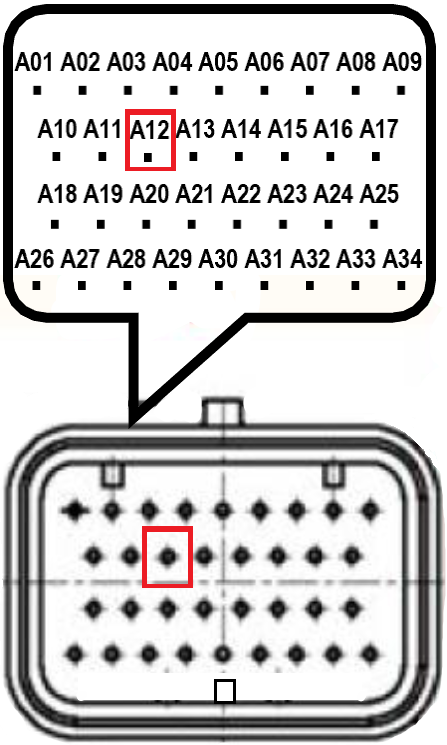 |
| A13 | Ignition Coil Cylinder 2 | Ignition Output 4 | 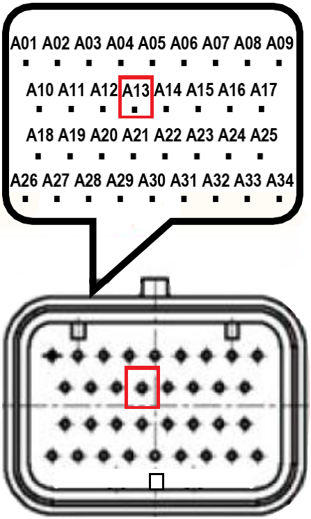 |
| A14 | Ignition Coil Cylinder 5 | Ignition Output 6 | 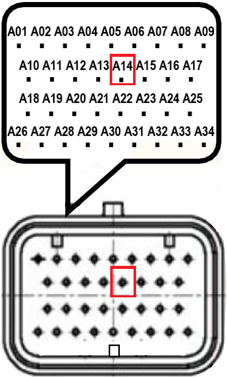 |
| A15 | Ignition Coil Cylinder 3 | Ignition Output 8 | 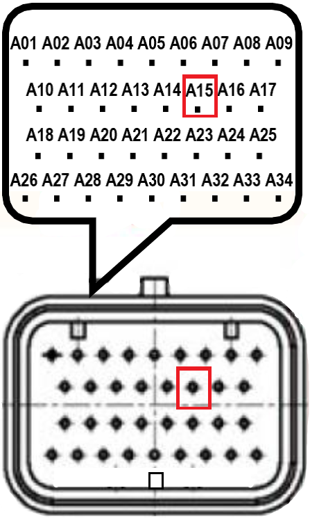 |
| A19 | Ignition Coil Cylinder 1 | Ignition Output 1 | 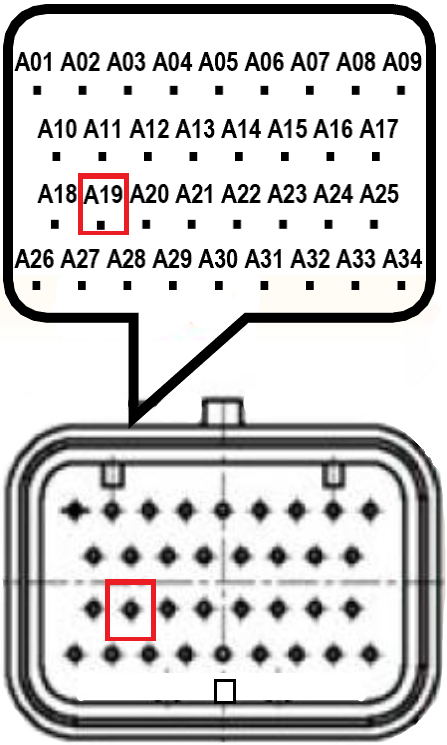 |
| A20 | Ignition Coil Cylinder 7 | Ignition Output 3 | 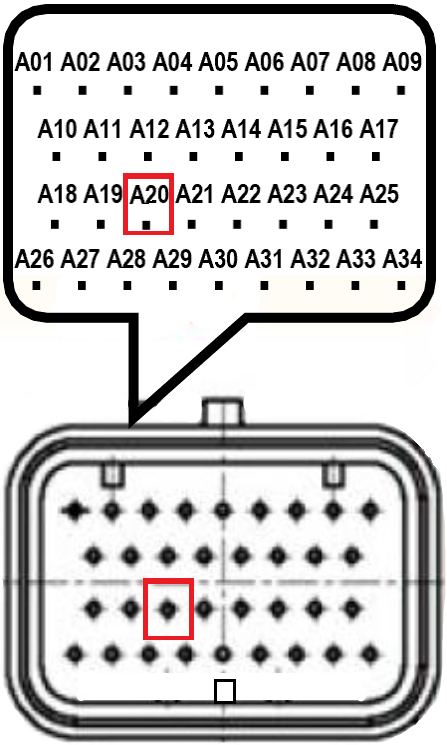 |
| A21 | Ignition Coil Cylinder 6 | Ignition Output 5 | 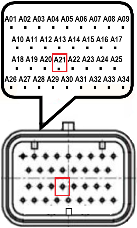 |
| A22 | Ignition Coil Cylinder 4 | Ignition Output 7 | 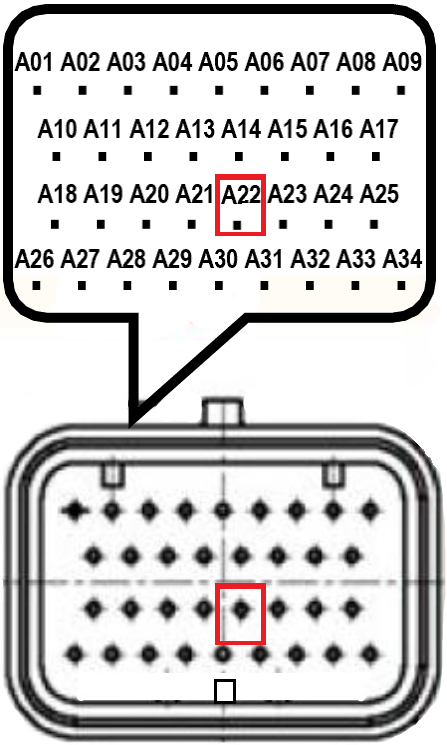 |
Injection Wiring🔗
| Pin # | Harness Output | Description | Pin "A" Location |
|---|---|---|---|
| A3 | Fuel Injector Cylinder 1 | Injection Output 1 | 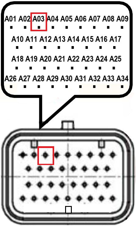 |
| A4 | Fuel Injector Cylinder 8 | Injection Output 2 | 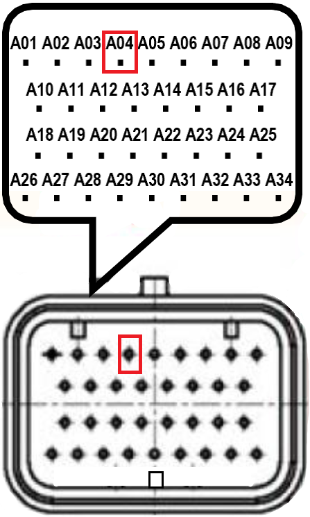 |
| A5 | Fuel Injector Cylinder 7 | Injection Output 3 | 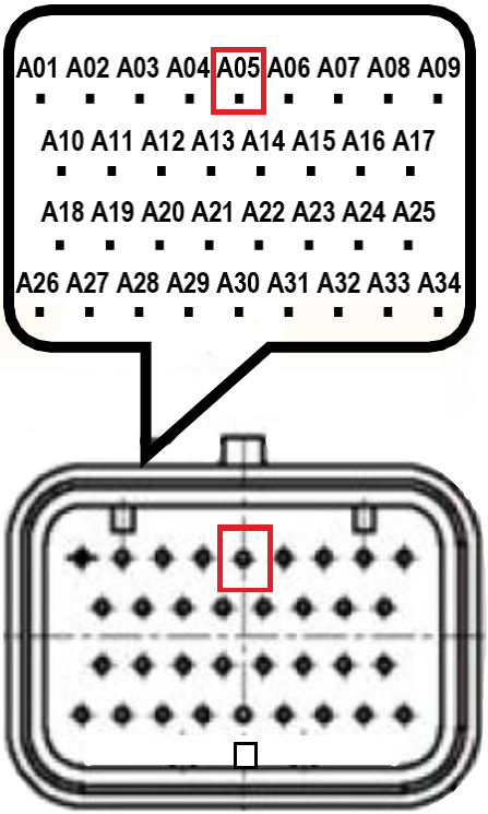 |
| A6 | Fuel Injector Cylinder 2 | Injection Output 4 | 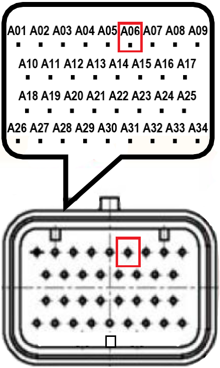 |
| A7 | Fuel Injector Cylinder 6 | Injection Output 5 |  |
| A30 | Fuel Injector Cylinder 3 | Injection Output 8 | 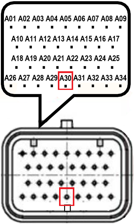 |
| A31 | Fuel Injector Cylinder 4 | Injection Output 7 | 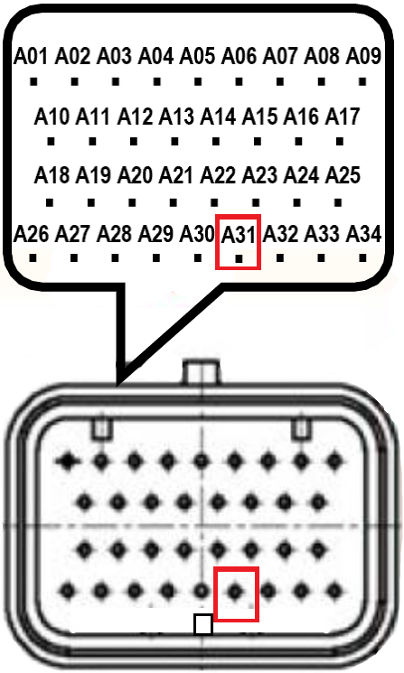 |
| A32 | Fuel Injector Cylinder 5 | Injection Output 6 | 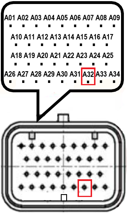 |