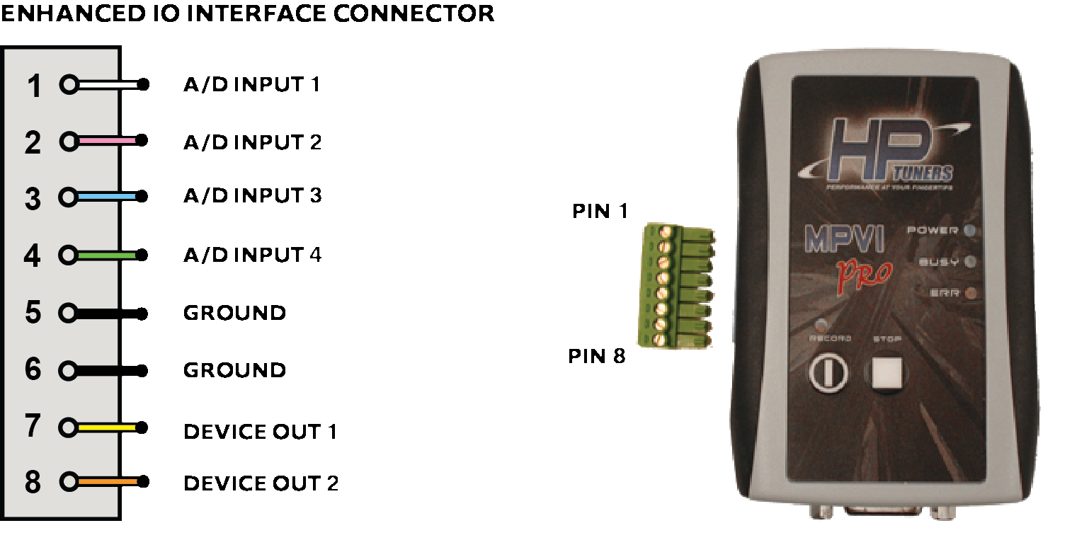
MPVI Interface Enhanced I/O Connector🔗
-
Four high impedance, buffered, filtered, 10 bit 0-5v analog to digital conversion channels that can connect to almost any device.Input impedance greater than 4meg ohm. A/D Inputs can tolerate short term voltage without damage.
-
Two ground reference tie points.
-
Two sink to ground 190 milliamp maximum each, continuous duty device drivers.
The analog inputs on the MPVI Pro's Enhanced IO connector can be used to attach up to four devices (such as many types of wideband sensor) that generate an analog output.
Devices Ouputs🔗
-
Control external devices by providing a ground when commanded on.
-
Driver circuits maximum current is 200 milliamps. Do not exceed these limits or you will damage the outputs.
-
Always use a 200 ma fuse in line with you connected device.
-
Blown output transistors will NOT be covered under warranty.
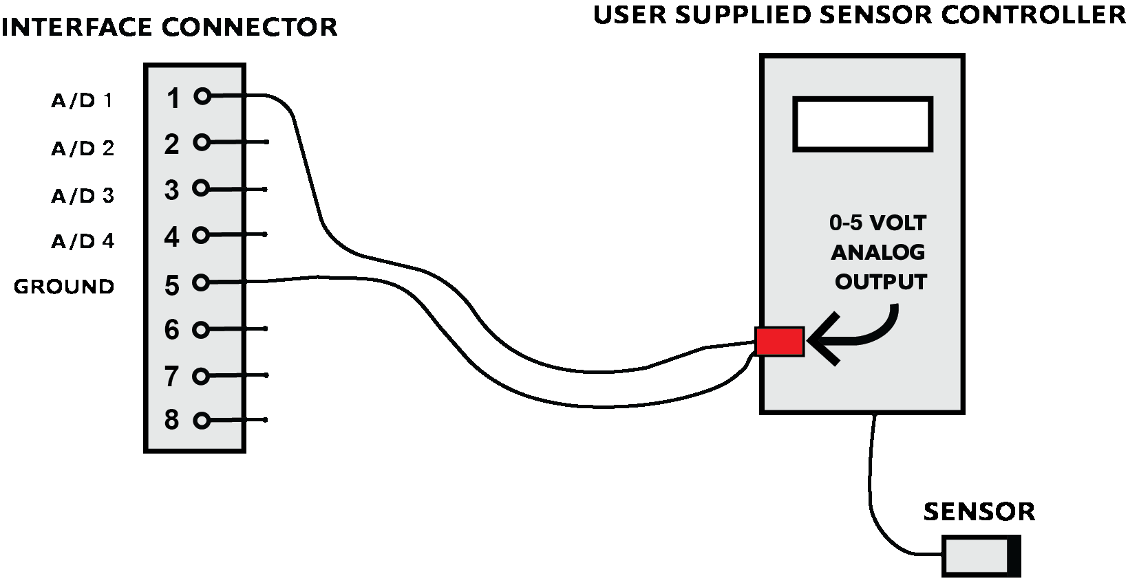
Connecting Analog Devices🔗
The following circuit shows the connection between the 0-5 volt analog output from an aftermarket wide band controller or EGT sensor (Exhaust Gas Temperature) using the supplied pigtail connector.
Refer to the manufacturer’s documentation on how to connect and configure their device.
The analog signal may be connected to any of the four inputs.
Driving Relays🔗
The Following circuit uses a Bosch Automotive Relay, part number 0-332-204-150.
-
When and how the relay(s) turns on and off by tracking any engine variable or A/D channel value is configured in the VCM Scanner program.
-
They can be used as a status indicator or external high current device control.
-
NEVER use the interface to control relays where safety is an issue or vehicle damage may occur.
-
Do not forget to add the driver protection fuse.


Driving LEDs🔗
The Following circuit uses a Radio Shack 276-272 12v Led with built in resistor and a Radio Shack 272-331 Panel Lamp using the supplied pigtail connector.
-
When the light(s) turns on and off by tracking an engine or A/D channel values are configured in the VCM Scanner program.
-
You can use any type of light/color you want as long as it does not draw more than 150 milliamps when lit.
-
If it does you will need to add a driver relay to isolate the interface unit from the larger current draw (see driving a relay diagram).
-
Do not forget to add the driver protection fuse.
