CORE AI Traction Control🔗
Below outlines the recommended procedures to utilize both AI traction control and Conventional traction control.
Artificial Intelligence (AI) Traction Control🔗
CORE's AI traction control maintains traction within a defined limit (Intelligent TC Slip Setpoint in mph) by reducing engine torque output through the following methods:
- Ignition (spark)
-
Injection (fuel)
-
Download the latest VCM Live (Beta) software.
-
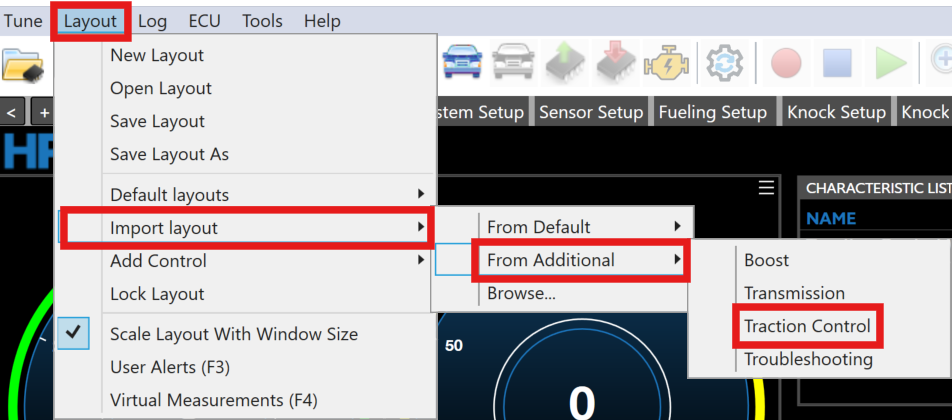
From the Menu Bar click Layout > Import Layout > From Additional > Traction Control.
-
Ensure the below parameters are selected, then click Ok.
-
In the layout menu bar select the Vehicle & Wheel Speed Setup tab.
-
Ensure at least one Front & Rear Speed Sensor Fitted parameter is set to Yes.
Note
Two Front & Rear Speed Sensor Fitted parameters can be set to Yes but only one for each need to be fitted to allow conventional traction control to work.
-
Ensure both Front Wheel 1/2 (FL/FR) Wheel Speed Sensor Input & Rear Wheel 1/2 (RL/RR) Wheel Speed Sensor Input parameter is set to one of the eight correct corresponding channels.
-
Ensure the Number of Teeth on Wheel is set to the correct value.
-
Ensure the Vehicle Tire Diameter is set to the correct value.
-
Ensure the Rear End Gear Ratio is set to the correct value.
-
Both Front Wheel Speed Selection Mode & Rear Wheel Speed Selection Mode need to be set to the following desired values:
- Average - Outputs average of front/rear wheel 1 (left) & rear wheel 2 (right) speeds.
- Minimum - Outputs minimum of front/rear wheel 1 (left) & rear wheel 2 (right) speeds.
- Maximum - Outputs maximum of front/rear wheel 1 (left) & rear wheel 2 (right) speeds.
-
Click the Traction Control Setup layout tab.
-
Ensure the Traction Control Mode parameter is set to IntelligentTC.
-
Select the corresponding Drive Type.
-
If you are utilizing any sort of switch to arm traction control, ensure to set the Traction Control Arming Switch Fitted parameter to Yes.
-
Ensure to set the Traction Control Arming Switch Sensor Input to the correct switch type value.
-
Set the Traction Control Vehicle Speed Threshold to the desired mph you want AI traction control to be enabled.
-
Set the Traction Control Vehicle Speed Threshold Hysteresis to the desired mph you want AI traction control to disable.
-
To adjust the desired wheel slip at different vehicle speeds, adjust the INTELLIGENT TRACTION CONTROL SLIP SETPOINT (MPH) table.
-
AI Traction control is now ready to be utilized.
Note
If any issues occur while using AI traction control, utilize the TC Ignition Cut Status parameters to DEBUG any issues.
Conventional Traction Control🔗
CORE's conventional traction control calculates wheel slip and utilizes a proportional integral (PI) controller to keep the vehicle slip under a defined limit (slip setpoint %) by reducing engine torque output through the following methods:
- Ignition (spark) - Retard timing and/or completely cut individual cylinders.
- Injection (fuel) - Completely cut individual cylinders.
- Throttle Correction - Partially reduce the throttle position (partially close).
-
Boost Wastegate Correction - Partially reduce the boost wastegate duty cycle or lower the boost setpoint.
-
Download the latest VCM Live (Beta) software.
-
From the Menu Bar click Layout > Import Layout > From Additional > Traction Control.
-
Ensure the below parameters are selected, then click Ok.
-
In the layout menu bar select the Vehicle & Wheel Speed Setup tab.
-
Ensure at least one Front & Rear Speed Sensor Fitted parameter is set to Yes.
Note
Two Front & Rear Speed Sensor Fitted parameters can be set to "Yes" but only one for each need to be fitted to allow conventional traction control to work.
-
Ensure both Front Wheel 1/2 (FL/FR) Wheel Speed Sensor Input & Rear Wheel 1/2 (RL/RR) Wheel Speed Sensor Input parameter is set to one of the eight correct corresponding channels.
-
Ensure the Number of Teeth on Wheel is set to the correct value.
-
Ensure the Vehicle Tire Diameter is set to the correct value.
-
Ensure the Rear End Gear Ratio is set to the correct value.
-
Both Front Wheel Speed Selection Mode & Rear Wheel Speed Selection Mode need to be set to the following desired values:
- Average - Outputs average of front/rear wheel 1 (left) & rear wheel 2 (right) speeds.
- Minimum - Outputs minimum of front/rear wheel 1 (left) & rear wheel 2 (right) speeds.
- Maximum - Outputs maximum of front/rear wheel 1 (left) & rear wheel 2 (right) speeds.
-
Click the Traction Control Setup layout tab.
-
Ensure the Traction Control Mode parameter is set to ConventionalTC.
-
Select the corresponding Drive Type.
-
If you are utilizing any sort of switch to arm traction control, ensure to set the Traction Control Arming Switch Fitted parameter to Yes.
-
Ensure to set the Traction Control Arming Switch Sensor Input to the correct switch type value.
-
In the layout menu bar select the CTC2.0 tab.
-
When tuning traction control, SLIP SETPOINT (%) is the table needed to tune traction control efficiently.
-
To adjust/correct the response of the controller (Slip Setpoint (%)) users need to change the values on both TRACTION CONTROL CYLINDER IGNITION CUT COUNT (# OF CYLINDER TO CUT) & TRACTION CONTROL CYLINDER INJECTION CUT COUNT (# OF CYLINDER TO CUT).
Note
- Conventional traction control can retard the spark timing on low over-slip conditions and completely cut individual cylinder spark on high slip conditions. Tuners can adjust the phase 1 spark retard with the Traction Control Ignition Retard table.
- The Traction Control Ignition Retard table top axis represents low over-slip and the cylinder ignition cut count table top axis represents high over-slip.
-
Conventional traction control is now ready to be utilized.