CO₂ Boost Control🔗
Below outlines the recommended procedures to utilize both CO₂ and Timed Boost Control.
CO₂ Boost Control Calibration🔗
VCM Live along with CORE offer four CO₂ boost control modes. All modes can be configured with or without dome pressure inputs. CORE efficiently manages the fill and exhaust wastegate valves to achieve effective boost control. Upon deactivation, CORE automatically drains boost pressure, ensuring the system is ready for the next operation. The four CO₂ boost control modes are as follows:
-
Open loop CO₂ boost control
-
Close loop CO₂ boost control
-
Timed open loop CO₂ boost control
-
Timed close loop CO₂ boost control
Note
CORE provides dual over-boost protection including the following:
- Over boost soft limiter: Ensure to adjust parameters such as spark, throttle position (Drive-By-Wire & Dual throttle setups), and wastegate duty cycle to prevent excessive boost.
- Over boost hard limiter: Acts as the final safeguard to ensure boost pressure remains within safe limits, preventing mechanical damage.
-
Download the latest VCM Live (Beta) software.
-
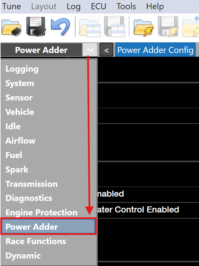
Open VCM Live and click the drop down arrow in the group layout tab and select Power Adder.
-
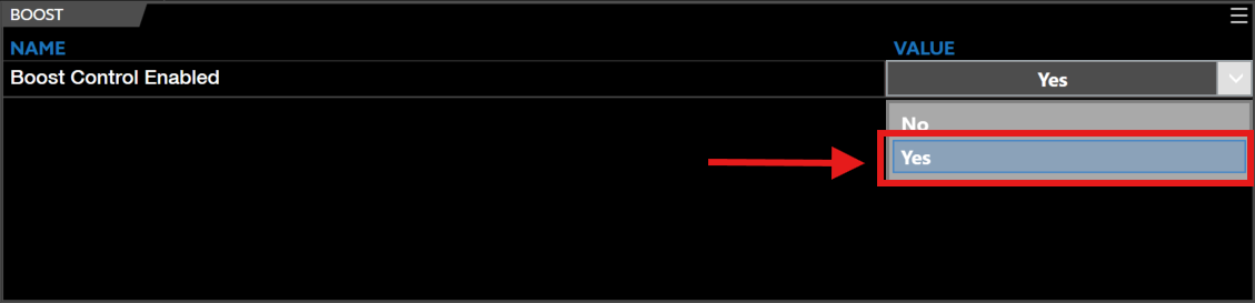
Locate the Boost Control Enabled parameter and select Yes.
-
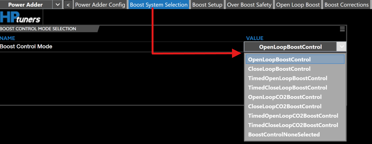
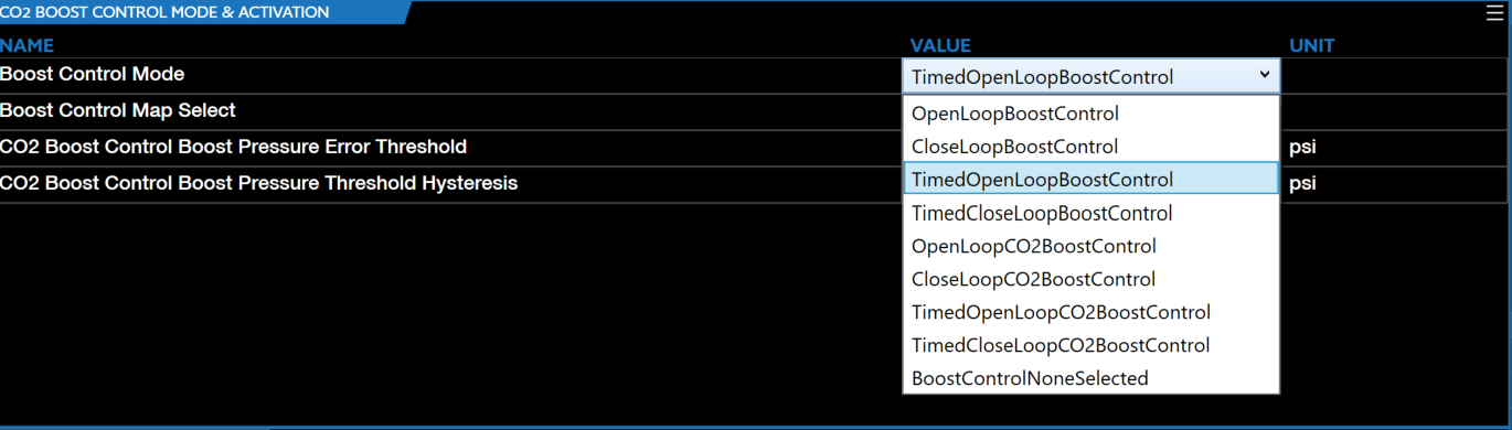
Once boost control is enabled the top group layout menu will display the corresponding tabs, select the Boost System Selection tab and select your desired CO₂ Boost Control Mode.
-
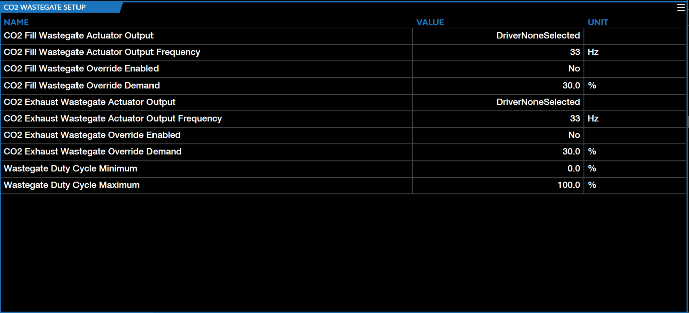
Adjust the CO₂ WASTEGATE SETUP parameters accordingly and ensure all channels are wired and the corresponding channels are set accordingly.
-
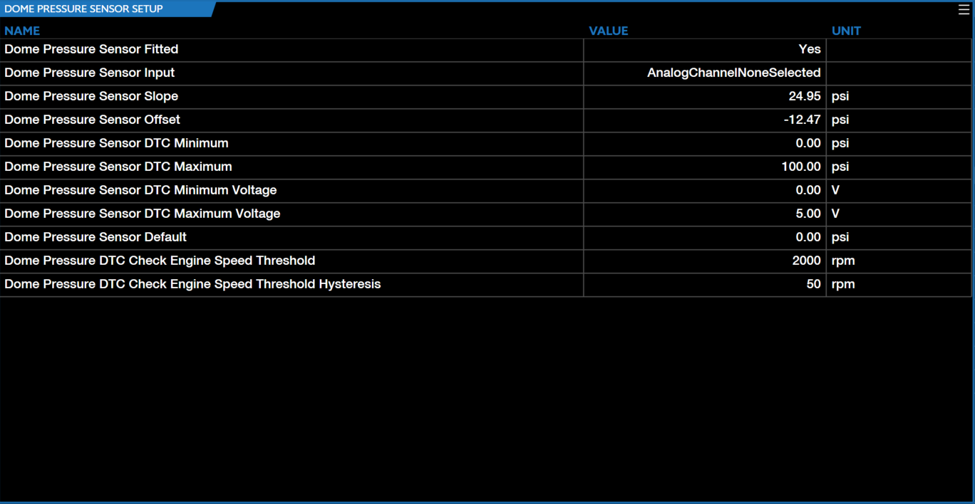
Adjust the DOME PRESSURE SENSOR SETUP parameters accordingly and ensure all channels are wired and the corresponding channels are set accordingly.
-
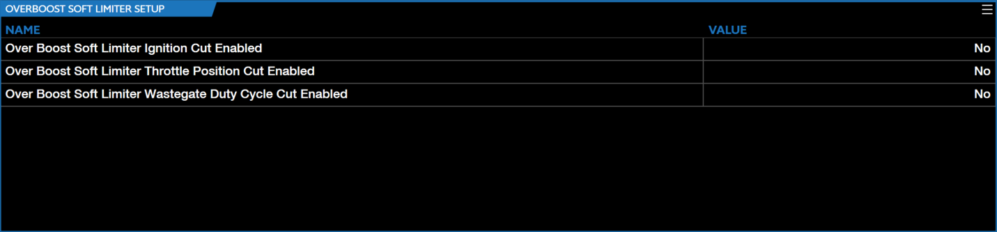
Adjust the OVERBOOST SOFT LIMITER SETUP parameters accordingly.
-
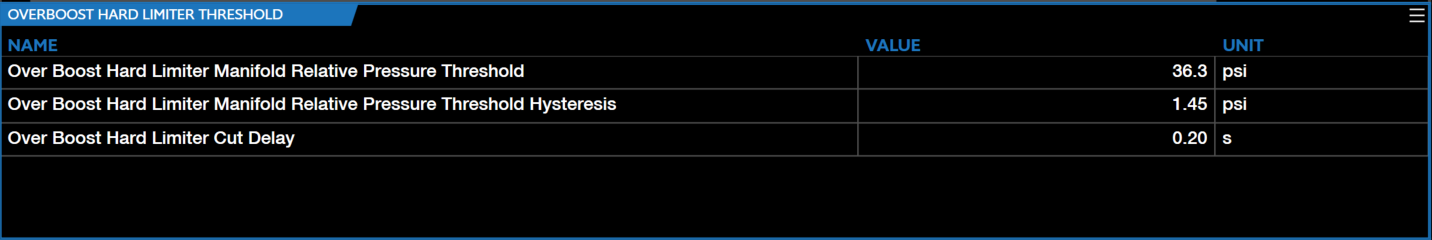
Adjust the OVERBOOST HARD LIMITER THRESHOLD parameters accordingly.
-
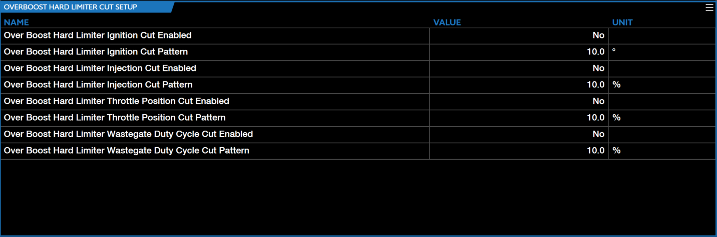
Adjust the OVERBOOST HARD LIMITER CUT SETUP parameters accordingly.
-
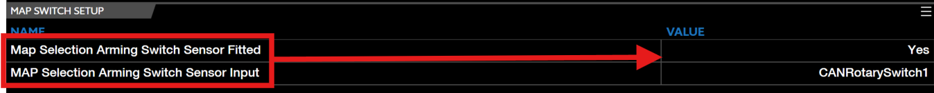
Ensure the MAP Selection Arming Switch Sensor Fitted is set to Yes and the correct channel input is selected.
-
Select the corresponding CO₂ Boost Control Mode.
-
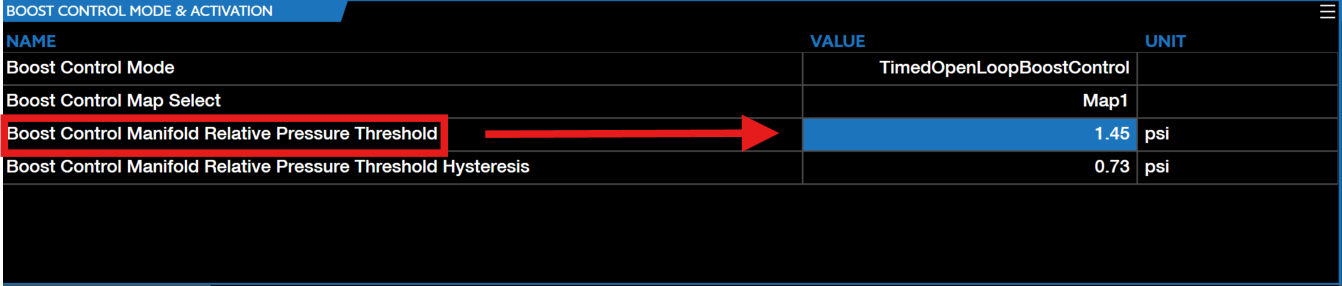
Set the Boost Control Manifold Relative Pressure Threshold to the desired value you want boost control to enable.
Note
Values above the CO₂ Boost Control Boost Pressure Error Threshold will reset the integral of closed loop CO₂ boost control.
-
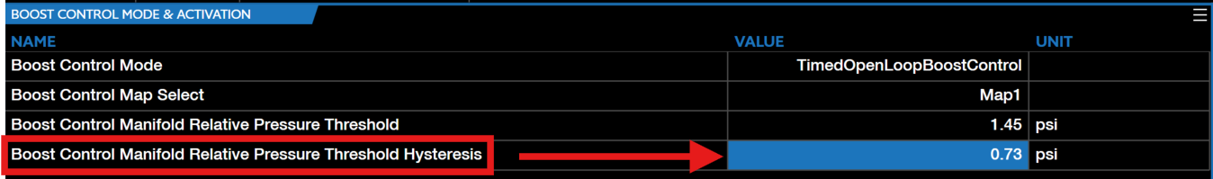
Set the Boost Control Manifold Relative Pressure Threshold Hysteresis to the desired value you want boost control to disengage.
-
Select the CO₂ Boost Tuning tab.

Note
This tab is where CO₂ boost can be montiored and live tuned.
-
The Boost Pressure Setpoint (PSI) table is a function of engine speed and throttle position, utilize this table to tune both parameters accordingly.
Note
Users can utilize throttle position cuts, ONLY for Drive-By-Wire (electronic throttle body) setups.
-
CO₂ boost control is now ready to be utilized.
Timed CO₂ Boost Control Calibration🔗
Timed Boost Control operates in conjunction with the standard boost control activation criteria, incorporating an additional timed activation mechanism. This mechanism uses either the timed boost arming switch or the clutch pedal (depending on the transmission type) to enable boost control. VCM Live along with CORE offer four Timed Boost Control Modes, those modes are as follows:
- Timed open loop boost control
- Timed close loop boost control
- Timed open loop CO₂ boost control
- Timed close loop CO₂ boost control
Note
CORE applies dual over-boost protection to all Timed Boost Control modes.
-
Download the latest VCM Live (Beta) software.
-
Open VCM Live and click the drop down arrow in the group layout tab and select Power Adder.
-
Locate the Boost Control Enabled parameter and select Yes.
-
Once boost control is enabled the top group layout menu will display the corresponding tabs, select the Boost System Selection tab and select your desired Timed CO₂ Boost Control Mode.
-
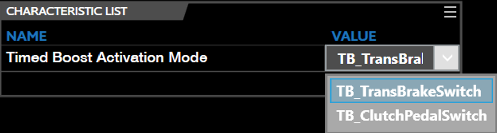
Locate the Timed Boost Activation Mode characteristic parameter and select the activation mechanism you would like to enable boost control with (TB_TransBrakeSwitch or TB_ClutchPedalSwitch).
-
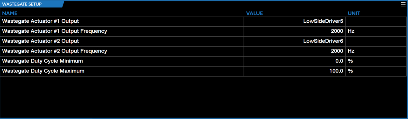
Adjust the WASTEGATE SETUP parameters accordingly and ensure all channels are wired and the corresponding channels are set accordingly.
-
Adjust the DOME PRESSURE SENSOR SETUP parameters accordingly and ensure all channels are wired and the corresponding channels are set accordingly (if applicable).
-
Adjust the TIMED BOOST SWITCH SETUP parameters accordingly and ensure all channels are wired and the corresponding channels are set accordingly.
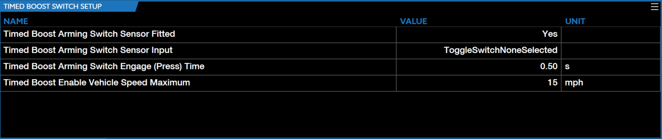
Note
A Timed Boost Switch is REQURIED in order to utilize the above parameters.
-
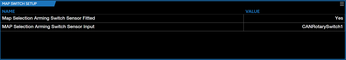
Adjust the MAP SWITCH SETUP parameters accordingly.
-
Adjust the OVERBOOST SOFT LIMITER SETUP parameters accordingly.
-
Adjust the OVERBOOST HARD LIMITER THRESHOLD parameters accordingly.
-
Adjust the OVERBOOST HARD LIMITER CUT SETUP parameters accordingly.
-
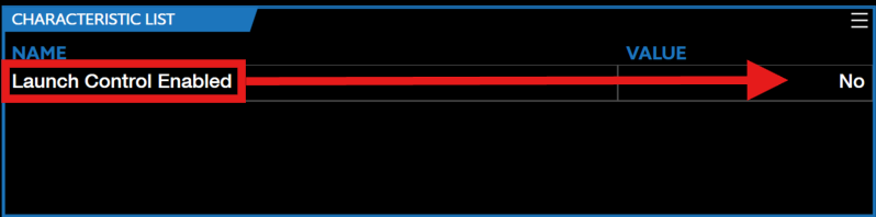
Ensure Launch Control Enabled is set to No.
-
Select the corresponding Timed Boost Control Mode.
-
Set the Boost Control Manifold Relative Pressure Threshold to the desired value you want boost control to enable.
-
Set the Boost Control Manifold Relative Pressure Threshold Hysteresis to the desired value you want boost control to disengage.
-
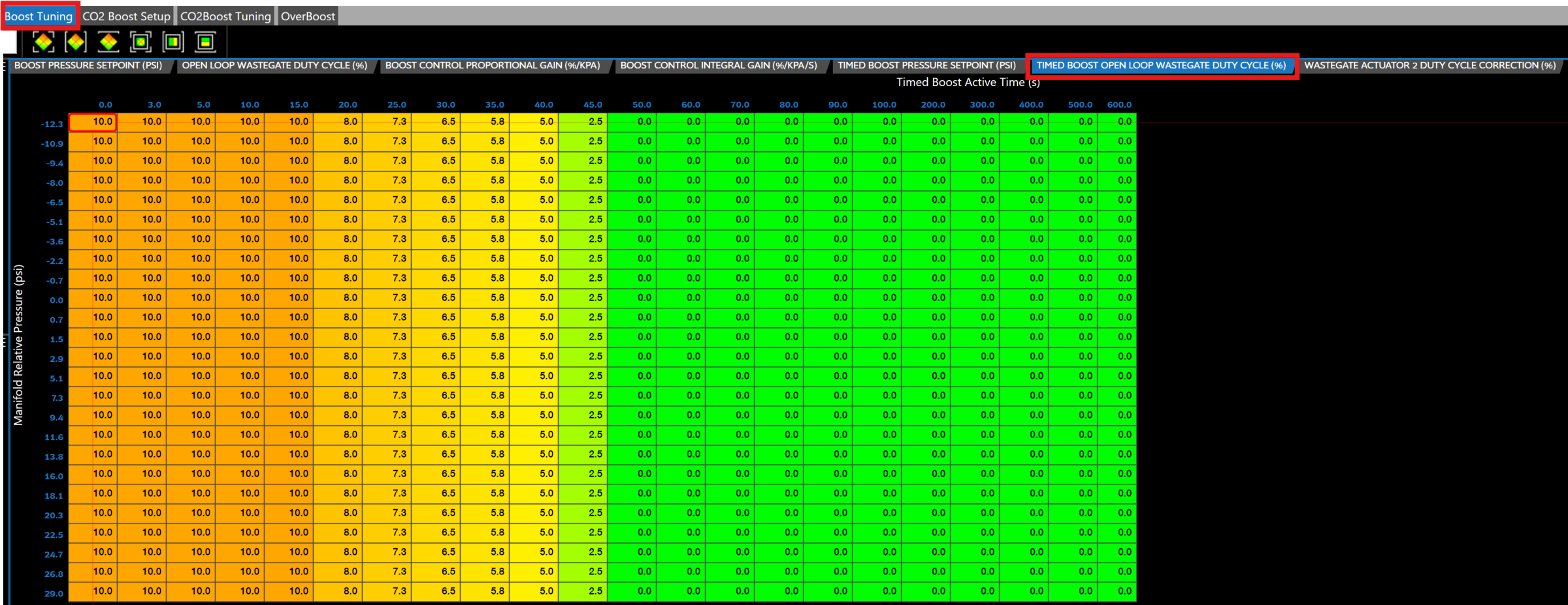
Select the Boost Tuning tab in the menu bar.
-
Adjust the baseline threshold by setting the TIMED BOOST OPEN LOOP WASTEGATE DUTY CYCLE (%) parameter accordingly.
-
Set the TIMED BOOST PRESSURE SETPOINT (PSI) accordingly.
Note
These timed boost modes are functions of throttle position and timed boost active time.
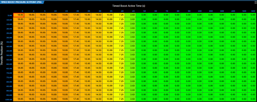
Note
The above table/system will maintain the boost demand specified at the last point in the able. It is recommended to set a safe boost value for the last point to ensure reliability and avoid potential issues.
-
Adjust the below parameters accordingly.
Note
Both the engine RPM and manifold relative pressure must exceed their respective threshold values for boost control activation.
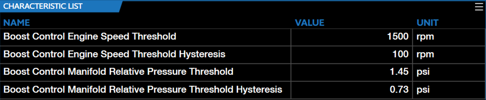
Note
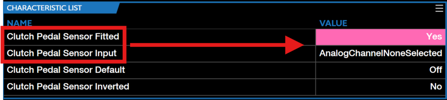
If operating with a manual clutch, ensure the Clutch Pedal Sensor Fitted parameter is set to Yes and the corresponding channel is fitted correctly.
-
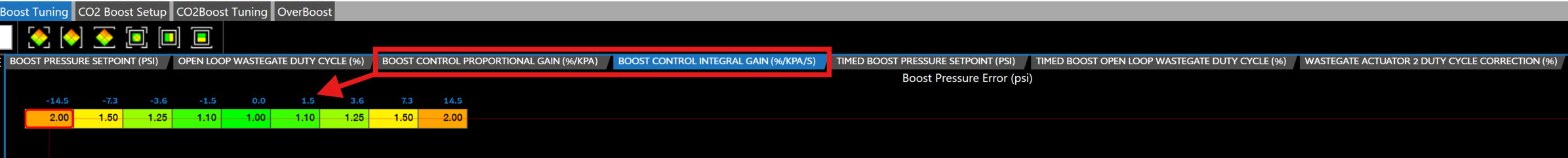
To live tune timed boost control adjust BOOST CONTROL PROPORTIONAL GAIN (%/KPA) & BOOST CONTROL INTEGRAL GAIN (%/KPA/S) accordingly.
-
Timed boost control is ready to be utilized.